Construction and functionalities of traction substation power switchgear
 Application of an electrical switchgear
What are traction substation power switchgears used for?
Traction substations are designed to transform electricity supplied by local DSO companies (Distribution System Operator, formerly power plants) or the own network of railway carriers, to the parameters appropriate for powering the railway system (via rail or overhead line – catenary).
It should be noted that the voltage supplying the traction network, depending on the adopted traction power supply system (for different countries/carriers), may have different values. The traction network can be supplied with direct current (DC) or alternating current (AC).
An important element of the traction substation is the power switchgear. The power supply or transmission line is connected to it and its task is to distribute energy to specific receivers. In this case, the energy can be used for own needs (supply of traction substation technological loads: heating, lighting), go to processing units – rectifier units (transformer/rectifier) or to non-traction receivers (supply of auxiliary devices: heating of turnouts, lighting of platforms).
Main parts of the power switchgear
Busbars are the most important element of each power switchgear. The power supply lines are connected to them on the energy side. On the receiver side, the receiving devices are connected. In addition, each switchgear on the supply side has:
1. Power switch/ circuit breaker – used for safety reasons. Its task is to break the circuit (disconnect the power supply) if there is an overvoltage or short circuit. It can also be used by the traction substation staff to perform service activities.
2. Earthing switch – another safety feature that is useful for service personnel when performing maintenance work.
3. Disconnect switch – its function is to open or close electrical circuits.
4. Voltage transformers – their task is to adjust the value of the voltage from the main network to the value appropriate for the connection and operation of measuring and control-protection equipment.
5. Current transformers – most often located in the feeder bay (however, they are often designed and installed in other bays). Their task is to adjust the current value to the needs of connection and operation of measuring and control and protection equipment. Thus, they supply the secondary circuit with a current proportionally reduced (compared to the current flowing in the primary circuit).
6. Lightning arrester – is used to protect the traction substation equipment from the possibility of damage caused by lightning. In general, the power supply or transmission line must be connected to the busbars via a circuit breaker and possibly a three-phase line disconnector. It should be noted that the construction of the entire system is similar on the receiving side.

Types of power switchgears
The construction of the traction substation power switchgear determines its division into:
- internal installed in the building
- overhead that is located in an open space
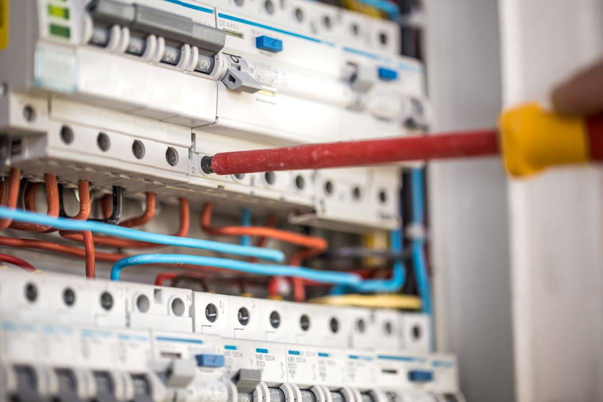
Indoor power switchgears are devices located in the substation building or in a separate room. The switchgear frame, to which individual bays are mounted, is permanently attached to the floor (made of concrete) of the traction substation. Indoor switchgears are in the form of free-standing cabinets/cells. Overhead power lines are usually led to the indoor switchgear through bushings insulators (mounted in the walls of the substation building). Another, equally frequently used solution is the power supply of the switchgear through cable lines (entered into the building through a sealing system installed in the external walls).
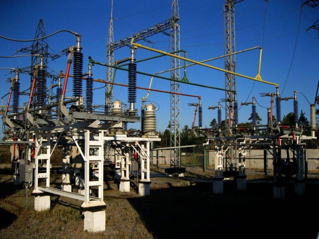
Overhead switchgears are mounted “in the air” on supporting structures. On these structures all the necessary switchgear equipment is mounted. Connection fields are mounted on one side of the switchgear, and receiver fields on the opposite side. In the middle, there are busbars. In this case, the entire device is exposed to the weather conditions. What’s more, the insulating factor is air, unlike indoor or built-in switchgear, where SF6 gas is most often used as insulation.
Installation of the power switchgear
Undoubtedly, the assembly of the power switchgear of the traction substation should be carried out by a company that employs qualified and properly trained employees. Only then, can you be sure that the switchgear will work properly and without failure. It is not without significance that the materials and components from which the switchgear is built are very important. Only high-quality accessories and their correct installation can guarantee reliable operation. Additionally, it is very important to ensure the safety of the switchgear operating personnel. Therefore, after its assembly, before commissioning, the design and correct assembly of the switchgear must be approved by professionals, i.e. power engineers with appropriate qualifications.iałanie. Nie mniej ważne jest zapewnienie bezpieczeństwa personelowi obsługi rozdzielnicy. Dlatego po jej montażu, przed oddaniem do użytku, konstrukcja i poprawny montaż rozdzielnicy musi zostać zatwierdzony przez profesjonalistów, czyli inżynierów energetyków z odpowiednimi uprawnieniami.